
* Online Price may be wrong or outdated and can NOT be used as proof by anyone or any organization for any purpose.
H831CCMA is a central control unit (CCU) board. It manages broadband and narrowband service boards and interface modules, and is used for upstream service transmission.
Functions and Specifications | H831CCMA |
|---|---|
Upstream transmission |
|
Ports on the front panel |
|
Daughter board | According to different daughter boards, the control board has the following hardware configurations:
|
Local and remote maintenance | Supported |
Environment monitoring port | Supported |
Boolean alarm port | Supported |
Synchronous clock transfer | Supported |
For details, see "Board Power Consumption".
Figure 1 illustrates the working principle of the H831CCMA board.
Figure 1 Working principle of the H831CCMA board
The basic working principle of the H831CCMA board is as follows:
The voice daughter board provides a built-in DSP chip, processes voice frequency signals, and converts digital signals into VoIP packets.
The clock daughter board supports time synchronization and tracking of the system clock.
The upstream processing module provides 2 SFP ports and supports GPON, XG-PON, GE, and 10GE upstream transmission.
The control and service processing module manages other components on the board through the management port, and provides service ports to connect to service boards and process services.
The logic module controls clock source selection and resets.
The power module controls the power provided through the backplane for feeding each component of the board.
The clock module provides the working clock signals for other function modules of the board.
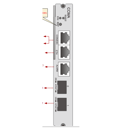
Figure 2 Ports on the front panel of the H831CCMA board
![]() NOTE:
NOTE:
Different optical modules can be configured to meet requirements of different application scenarios.
For details on parameters and types of optical modules, see "Optical Module".
The CONSOLE/ESC port (RJ45 port) is connected to the maintenance terminal and environment monitoring device using the local maintenance and environment monitoring combo cable.
Silk Screen | Name | Color | Status | Meaning |
|---|---|---|---|---|
RUN/ALM | Operating status indicator | Green | Blinking quickly (on for 0.25s and off for 0.25s repeatedly) | The board is being loaded during startup. |
| Green | Blinking slowly (on for 1s and off for 1s repeatedly) | The board operates normally. | ||
| Red | On | The board is faulty. | ||
SYNC | Synchronization status indicator | Green | On | The system is synchronized. |
| Red | On | The system is not synchronized. | ||
LINK | Link status indicator (GE optical port and PON optical port) | Green | On | The link is normal and a connection is set up on the port. |
| Green | Off | The link is abnormal and no connection is set up on the port. | ||
ACT | Data status indicator (GE optical port) | Green | Blinking | Data is being transmitted. |
| Green | Off | No data is being transmitted. | ||
AUTH | Authentication indicator | Green | Blinking (on for 0.25s and off for 0.25s repeatedly) | An authentication is being performed. |
| Green | On | The authentication is successful. | ||
| Green | Off | No authentication is being performed. | ||
ETH | ETH port status indicator | Green | On | A connection is being set up on the port. |
| Green | Off | No connection is set up on the port. | ||
| Yellow | Blinking | The port is transmitting data. | ||
| Yellow | Off | No data is being transmitted. |
Table 2 shows the pin assignment of the ALARM port on the front panel of the H831CCMA board.
Port | Pin | Signal | Default Setting |
|---|
Port | Pin | Signal | Default Setting |
|---|---|---|---|
| 1 | RTN | - |
2 | MONITOR 0 | ||
3 | RTN | Door status sensor | |
4 | MONITOR 1 | ||
5 | RTN | Surge protector | |
6 | MONITOR 2 | ||
7 | RTN | Main distribution frame (MDF) | |
8 | MONITOR 3 |
![]() NOTE:
NOTE:
Default settings in Table 2 are recommended values. In practice, the ALARM port is connected to various types of Boolean value output sensors as required.
When the default setting of a pin is different from the actual sensor corresponding to the pin, the default setting needs to be changed using the CLI so that it is the same as the actual setting.
Each Boolean value output sensor corresponds to a pair of pins. In the case of a short circuit, the corresponding digital parameter is 0; in the case of an open circuit, the corresponding digital parameter is 1.


