

* Online Price may be wrong or outdated and can NOT be used as proof by anyone or any organization for any purpose.
The H901MPSCE board is a control board. It is the core of the system control and service switching and aggregation. The H901MPSCE board can also function as the management and control core of the integrated network management system (NMS). It exchanges the key management and control information with service boards through the master/slave serial port and in-band channel. In this manner, the H901MPSCE board configures, manages, and controls the device, and also provides simple dynamic routing.
Figure 1 Appearance
Please refer to "Comparison of Control Boards".
Parent Topic: Control Board

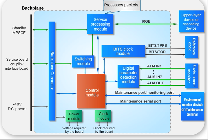
Figure 2 Working principle of the H901MPSCE board
| Indicates the control signal channel. |
| Indicates the service signal channel. |
| Control module: manages the entire board and the service boards, and communicates with the fan tray through the extended serial port. |
|
|
| Indicates the power or clock signal channel. |
|
|
Parent Topic: Control Board

For details about supported optical module, see 10GE Optical Module and GE Optical/Electrical Module.
Parent Topic: Control Board
Indicator | Name | Color | Status | Meaning |
|---|---|---|---|---|
RUN/ALM | Running status indicator | Green | Blinking slowly (on for 1 s and off for 1 s repeatedly) | The board functions properly |
Green | Blinking quickly (on for 0.25 s and off for 0.25 s repeatedly) | Indicates that program loading is in progress | ||
Orange | Blinking | A high-temperature alarm is generated | ||
Red | On | The board is faulty | ||
Red | Blinking (on for 0.25 s and off for 0.25 s repeatedly) | The board is starting up | ||
ACT | Load sharing status indicator | Green | On | The board is active |
Green | Blinking (on for 1 s and off for 1 s repeatedly) | The board is standby | ||
Red | On | If load sharing is abnormal, the board is in active state | ||
Red | Blinking (on for 1 s and off for 1 s repeatedly) | If load sharing is abnormal, the board is in standby state | ||
CRI | Alarm indicators | Red | On | The system has generated a critical alarm |
MAJ | Orange | On | The system has generated a major alarm | |
MIN | Yellow | On | The system has generated a minor alarm | |
L/A 0-3 | Link/data status indicator | Green | On | A connection is set up on the port |
Green | Blinking | Data is being transmitted | ||
- | off | No connection is set up on the port |
Parent Topic: Control Board
Port | Pin | Signal | Remarks |
|---|---|---|---|
| 1 | ALM_RTN | Alarm digital parameter RTN |
2 | ALM_IN0 | Channel 0 alarm digital parameter signals | |
3 | ALM_RTN | Alarm digital parameter RTN | |
4 | ALM_IN1 | Channel 1 alarm digital parameter signals | |
5 | ALM_RTN | Alarm digital parameter RTN | |
6 | ALM_IN2 | Channel 2 alarm digital parameter signals | |
7 | ALM_RTN | Alarm digital parameter RTN | |
8 | ALM_IN3 | Channel 3 alarm digital parameter signals |
Port | Pin | Signal | Remarks |
|---|---|---|---|
| 1 | ALM_RTN | Alarm digital parameter RTN |
2 | ALM_IN4 | Channel 4 alarm digital parameter signals | |
3 | ALM_RTN | Alarm digital parameter RTN | |
4 | ALM_IN5 | Channel 5 alarm digital parameter signals | |
5 | ALM_RTN | Alarm digital parameter RTN | |
6 | ALM_IN6 | Channel 6 alarm digital parameter signals | |
7 | ALM_RTN | Alarm digital parameter RTN | |
8 | ALM_OUT | Alarm signal control output |
Port | Pin | Signal | Remarks |
|---|---|---|---|
| 1 | BITS_IN_B | Input B of channel BITS clock signals |
2 | BITS_IN_A | Input A of channel BITS clock signals | |
3 | PPS_IN/OUT- | Input or output negative polarity of PPS time signals | |
4 | BITS_OUT_B | Output B of the BITS clock signals | |
5 | BITS_OUT_A | Output A of the BITS clock signals | |
6 | PPS_IN/OUT+ | Input or output positive polarity of PPS time signals | |
7 | TOD_IN/OUT- | Input or output negative polarity of TOD time signals | |
8 | TOD_IN/OUT+ | Input or output positive polarity of TOD time signals |
![]() NOTE:
NOTE:
Input and output of PPS and TOD time signals use the same pin. These signals can only be input or output at a time.
Port | Pin | Signal | Remarks |
|---|---|---|---|
| 1 | ESC_RS485_TX+ | TX signal of the environment monitoring serial port |
2 | ESC_RS485_TX- | TX signal of the environment monitoring serial port | |
3 | CON_TX | TX signal of the maintenance serial port | |
4 | GND | GND | |
5 | GND | GND | |
6 | CON_RX | RX signal of the maintenance serial port | |
7 | ESC_RS485_RX+ | RX signal of the environment monitoring serial port | |
8 | ESC_RS485_RX- | RX signal of the environment monitoring serial port |
![]() NOTE:
NOTE:
The maintenance serial port CON and the environment monitoring serial port ESC share one interface and work in line splitting mode. In the case of dual control boards, the ESC ports on the two control boards are directly connected, and the lines must be split to avoid the interference between CON to the ESC ports.
Parent Topic: Control Board